Garrattfan's Modelrailroading Pages

LTM 51 in HO
Boiler cradle
- Introduction
- History of the LTM 51
- Inventory of the kit
- Instruction manual
- A preview
- Project preparations
- Boiler cradle - Main construction
- Pivots
- Boiler
- Drive units - Chassis
- Sprung frames
- Gearbox and motor
- Coupling rods
- Drive units - Superstructure
- First assembly and trial run
- Drive units - Detailing
- Boiler cradle - Detailing

In het Nederlands
When most parts had arrived and when I had completed NBDS 118, I intensified preparations for LTM 51. I had been staring at the etches for several times and at one moment I noticed I was procrastinating. So I took a deep breath and made a first cut in this exceptionally rare etch and with that these etches become even more rare as mine was no longer untouched. It almost felt like sacrilege.
History was written on 8 May 2020, 75 anniversary of VE Day, end of WW2 in Europe.
|
 |
Usually I start a project with the frame and drive. This is the most critical part of the build and often the most tedious one. The superstructure is the fun part and I reserve that for last. But at the start of this project I am still waiting for the gearboxes to arrive despite being ordered on 30 March. On the 8th of May I have not even had so much as a response from High Level Kits despite reminders. I do have good experiences with them and their products though, so I will wait. In the mean time I started with the boiler cradle. Eventually it all turned out well end the gearboxes were received in good order. |
|
Getting acquaintanced and figuring it all out |
|
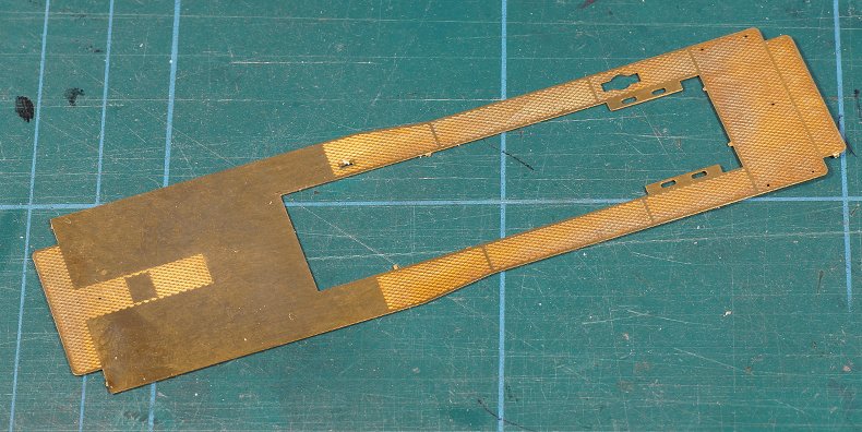
The very first part. The project now officially has started! |
|
After cutting all parts out of the boiler cradle fret I tried to figure out what went where. Remember I have no building manual whatsoever, so the parts should be more or less self explanatory. I studied each and every part carefully and really most parts are obvious. In the process I cleaned the parts up, removing burrs, etch cusps and fret bridges.
|
|
I was quite puzzled by the frame though. The "frame" of the boiler cradle, that is the running board, it supporting both vertical longitudinal braces and the lateral stretchers, left me with many questions.
|
|
A look at the drawing helped locate the Y-plates, but the location of the short Y-plate remained more or less a mystery. |
|
A conversation with a valued colleague builder revealed that the short Y-plate was presumably supporting the wooden cab floor. Note that the long Y-plate is halfway the spacers about to clear the boiler.
|
|
 |
This conversation also confirmed that the sagging spacers really needed to go on the end of the running board. The fact that they would protrude into the surface of the top plate of the drive unit had kept from accepting that but as it turned out the drive units had a recess at the rear end. Once you know it you can see it in the drawings.
This meant I had to make a choice: keep the spacers and cut out the top plate of the drive unit, or shorten the spacer. As space is at a premium below the top plate the cutting out and lowering the top plate will almost certainly interfere with the gearbocI chose the latter. |
 |
I had only one sagging spacer. The conclusion was that this was an error in the etch. There really should be two, one at each end of the boiler cradle. |
 |
So I got to work. An attempt to drill the holes on the Proxxon MF70 was unsuccessful. I mis-drilled by a huge 0.2 mm! Being not all to happy with the other hole I discarded it. |
 |
So out came the old fashioned piercing saw cum files. |
 |
And after two hours of delicate and careful sawing, drilling and filing I had a reasonable copy. Just guess which one is the original. |
So now I could go for a Blu-tack demonstration assembly. |
|
Constructing the actual cradle |
|
I have a habit of soldering running boards on a flat surface, in this case a sheet of safety glass. After each soldering action I can check if the running board is still flat. |
|
First I tack soldered the longitudinal braces on four spot ind the order (from left to right) 2, 4, 1, 3 It is of utmost importance to prevent heat build up in the three parts. They are long and they heat up they extend considerably. If let that unchallenged the running board will distort. I put every tack down quickly and after each tack let the running board cool down. In, out, cool down. "Nice and simple", as Bob Ross used to say. |
|
Aaaaaaaahhh! |
|
More tacks added inbetween the existing ones, each time letting the heat dissipate. |
|
 |
I checked the width between the braces. Where the short Y-plate neede to go everything was okay. |
 |
But at the front end a gap showed up. That was odd. I checked if the braces had followed the inner rim of the running board. I could find no fault. |
 |
 |
Measuring confirmed: 17.8 mm behind the boiler and 18.2 at the front. Now what? After careful consideration I decided to live with it. It will be invisible, in fact it already is, it only came to light when I checked. Altering the alignment would mean I would have to fill up the gap between the brace and the inner rim of the running board which might prove impossible to hide from sight. So get over it. |
|
|
|
So I filled in the soldering between the tacks and soldered the two Y-plates in place. |
|
Bending the cab sheetsActually I came to the stage where I wanted to fit the boiler to the frame of the boiler cradle, but the brass tube I had ordered had not arrived yet. I did some exercises with a steel tube but that did not turn out well. So I decided to wait for the brass tube to arrive and in the meantime do a few other jobs. |
|
 |
One of the future jobs is to bend the roof line of the cab's side sheets. This roof line has a relatively sharp bend that gradually eases into the roof itself. No easy bend to make.
I decide to make a bending jig which would be profiled using a template taken from the cab's backplate.
I scribed the roof contour on a scrap piece of 0.75 mm brass. I filed it out and made sure it matched the backplate's contour as close as I could get it. |
 |
I took a piece of angled aluminium and cut it somewhat longer then the roof top. |
 |
 |
| I filed the aluminium angle to match the brass template I had made. Time and again I touched the angle with the brass template. Especially against the light any discrepancies immediately came to light. | |
 |
When I was satisfied I matched the aluminium jig against the original and approved the result. Then why the template? Well, you can match the roof only on both outer ends of the aluminium jig. Even the most perfect match does not say anything about the rest of the profile. The template however can be held in any place to check the profile over the entire length of the jig. |
 |
 |
| I scribed a nearly invisible line on the cab's backplate where the corner started. I transferred the height of that line onto the cabside. I also scribed a corresponding line on the aluminium jig. | |
 |
I clamped the cab side in the vise with the aluminium jig behind it and aligned the two scribed lines. I checked for parallelism with my calipers. |
 |
Then I rolled the protruding end of the cabside over the form exerting even pressure with the another piece of aluminium angle. |
 |
 |
| Preparation: one and a half hours, actual operation: 10 seconds | |
 |
 |
| If I may say so: a next to perfect fit. The other cabside followed suit. | |
 |
While at it, I also shaped the roof to fit the rear and the front sheet of the cab. Again a line was scribed to locate and align the centers of both sheets. I rolles a steel bar over de inside of the roof on the cutting mat. Doing so it start to curve gently. The curve is very shallow so when starting out to form the roof start gently. |
Making the pivots |
|
At this stage I turned my attention to making the pivots that will connect the boiler cradle to the power units.
This became an adventure and project in itself so I dedicated a separate page to the subject of making the pivots. For here I suffice to show the end result. |
|
 |
 |
Boiler making |
|
| By now the brass tube I had ordered had arrived so I could get to work on the boiler. (28-05-2020). This, like the pivots was a small project in itself, so again I dedicated a separate page on boiler making. | |
The new boiler with smokebox door in the boiler cradle. |
|
Adding the firebox |
|
| No matter how you look at it, adding the firebox to the boiler was not going to be an easy job. After all you are matching a more or less square object to a round object with very little reference. And indeed it became a challenging journey. | |
 |
 |
| The rear sheet, links, forming the boiler backhead for starters would not fit the frame straight from the etch. The lower front end however did. | |
 |
So I drew some dimension lines and filed the firebox rear sheet to to fit in the frmae with about 1.0 mm to spare. This 2 x 0.5 mm provide for the room needed to attach the side panels and still fit in the fit after that. Ouch, that would have been a pitfall if you would not think ahead. |
Firebox assembled. Checking it against a square after the first assembly I found considerable skewness. I took out the gas burner and detached the parts again. During the second attempt I knew where to look for and the result was square. |
|
Filed flush and all cleaned up. |
|
 |
 |
 |
A V-slot was filed in the front and rear sheets, to allow for some tubes to pass under the ashpan.
This V-groove is clearly on the drawing, but I made a simplification by not mimicking the vertical step. |
The ashpan sheets were then soldered in. |
|
Leveling the boiler |
|
| Matching the boiler to the frame of the boiler cradle may seem like a very straight forward job. There were a few complications though. | |
First of all my calibrated eye (thanks Keith Appleton for the term) already spotted the boiler did not sit straight on the frame. One tell-tale was that the smokebox would not rest on the supports in the yellow oval. I thought of several ways to confirm this. I have no height gauge (yet). So I drew up this millimeter scale, printed it and glued it to a sheet of styrene. With a bit of careful work I could make a reasonably accurate scale. This scale made it clear the boiler was off by about 1.5 mm. The cab front sheet (spectacle plate for UK readers) revealed that the boiler would be lifted a few tenths once this front sheet was in place but even so the smokebox would be visibly too high. First I determined the desired height from the drawing to be 18.9 mm. Then I set to work to find causes and remedies. |
|
Long story short, I found the Y-plate assembly in the middle of the frame to be 0.5 mm to high. |
|
Left stretcher already filed, right one in preparatory stage. |
I considered my options. I could not just file 0.5 mm from the top of the stretchers. The horizontal Y-plate was 0.4 mm thick and it should not obscure the holes in the stretchers. Therefore the material left above the middle hole could be no less than 0.4 mm. That in turn meant I could take only 0.2 mm off from the curved top side of the stretcher (red line). Another 0.3 mm could be gained by filing off the straight bottom side (yellow line). That said I unsoldered the Y-plate assembly, duly filed the stretchers en resoldered it. |
 |
 |
Using a glass plate as a guaranteed flat surface reference I took great care to position the leading stretcher absolutely flush with the lower end of the boiler cradle. Apart from that the stretcher should also be true to the length and the height. I clamped it to an engineering square using a piece of round stock, a rubber band and half a laundry peg to hold the part. Once happy with the position of the stretcher I tack-soldered it in place. |
|
 |
Not pretty but I will clean it up once I determined the stretcher is in the correct position. |
 |
I test fitted the boiler and ooof, the first impression was encouraging. The smokebox settled down on its supports without the slightest hesitation Any remaining slant of the boiler escaped my calibrated eye. |
The final check was against the measuring template I made. I could see no significant difference. It looks a tad lower at the firebox side, but 1) the firebox is 0.2 mm less in diameter than the smokebox and 2) the firebox will raise a little when it is paired with the cab front sheet. |
|
 |
 |
| I now tack-soldered the Y-plate and rear stretcher and checked again. When no significant errors were found I fully soldered the assembly. | |
And there sits a fully level boiler. |
|
Fitting the boilerNext job is to solder the boiler in place. But that again was easier said then done. A string of preconditions opened up before me.
|
|
Assembly collision of the cab front sheet and boiler. So I set out to assemble the core structure of the cab first to find the correct position of the front cab sheet starting from hte rear of the coal bunker |
|
One of the rare photos giving a clear shot of the coal bunkers |
The coal bunkers of the LTM 51 are oddities in Garratt-land. First they are located on the boiler cradle instead of the usual location on the rear drive units. No doubt this was necessitated by the wish to keep the inside motion accessible. Effectively this classes this Garratt as a Union Garratt and not a Garratt proper but oddly enough no source ever mentions this. Second the coal was housed in two separate bunkers with a passage in between. This was to allow the train guard to access the locomotive cab from the trailing coaches and vice versa. |
 |
 |
 |
The coal bunker inside and rear panels. I bent the sheets over a piece of 0.8 mm brass rod as this corner has a radius. The etch had a folding line that was etched too deep so an ungainly slit was visible. I soldered an end of the 0.8 mm brass rod in the slit with 240C solder. The slit did not close completely so I will have to fill it with Milliput in a later stage.
|
Offering up the coal bunkers sheets to the frame. At this stage all joins are tack-soldered. So far the accuracy of the etches was not very convincing so fillet soldering will only be done once I have established that everything lines up and is quare and true. |
|
 |
Lining up the right side panel and rear cab sheet relative to the coal bunkers. |
 |
Tack-soldering proved to be very prudent. Spot the problem? Despite being absolutely bent to 90 degrees and being perfectly aligned with the rear end of the running board, the coal bunker panels do not line up well with the door sides in the rear of the cab.
I took the coal bunkers off again and removed about 0.5 mm from the rear panels of the coal bunker so they would sit a little further from the middle. |
 |
Again I built the cab up with tack-soldering |
 |
And checked again with the cab rear sheet. |
 |
and yes now they lined up. A small solder tack put them in place. I checked parallelism of the corridor sides and with a tiny taper away from the door of just 0.07 mm I was quite content. |
 |
|
 |
Now at last the boiler and cab front sheet are offered up to the cab and boiler cradle. The front sheet was tack-soldered, the boiler however was for now left loosely in the frame. |
I took my time to look at the boiler cradle from all sides, for one simply to enjoy the sight but second to check and check again if there was anything amiss.
|
|
 |
|
 |
The cab was checked for squareness and trueness in every direction. I could find no significant faults.
|
| I also tack-soldered the boiler to the top of the cab front sheet. followed by a one final check of the boiler before final fillet-soldering the whole assembly. The boiler sat perfectly level on exactly the correct height relative to the running board.
All's well that ends well |
|
Now all joints of the cab were fillet-soldered carefully avoiding excessive build-up of heat in the part. |
|
This concludes the main construction of the boiler cradle. Next is detailing. For the record you will see two state portraits below. The chimney and dome are loosely placed. The roof is still loose to allow for placing of a detailed boiler backhead in a later stage. The bunker tops are also still loose to allow later placement of lead to weight the locomotive.
|
|
 |
|


Sign my
GuestBook